I Overview of Thermistors
Like Resistance Temperature Detectors(RTDs), thermistors are temperature-sensitive semiconductors whose impedance changes with temperature. Thermistors are manufactured from metal oxide semiconductor materials packed with glass or epoxy beads. Moreover, the typical nominal impedance value of thermistor is much higher than that of the RTD, which is from 2000Ω to 10,000Ω, so it can be used for lower current measurement.
Each sensor has a given nominal impedance, which is approximately processed according to a certain linearization, and this impedance varies proportionally with temperature. The thermistor has a negative temperature correlation coefficient (NTC) or a positive temperature correlation coefficient (PTC). The former one is more common, and the impedance decreases with increasing temperature, while the latter increases with increasing temperature.
You can use a PTC thermistor as a current-limiting device (instead of a fuse), or as a heating component for a small temperature-controlled furnace. The NTC thermistor (the subject of this article) is mainly used for temperature measurement, and is widely used in digital temperature adjusting devices or automobiles to monitor the temperature of the engine.
Typically, the thermistor has a high sensitivity (about 200Ω/ °C), which makes it very sensitive to the changes in temperature. Although the thermistor has a very high response rate, its use is limited to a temperature range up to 300°C. This characteristic and its high nominal impedance help to provide accurate measurements in lower temperature applications.
II How to Measure a Thermistor?
1. Selection of Connecting Method
Since the thermistor is an impedance device, you must apply an excitation source to it, and then read the voltage flowing through the terminal. The excitation source must be kept constant and of considerable accuracy.
You can connect the thermistor differentially to an analog input channel for temperature measurement. In other words, you must connect the thermistor to the + ve and -ve terminals of the analog input channel.
The thermistor can be used in 2-wire, 3-wire, or 4-wire configurations, and their connections are shown in Figure 2.
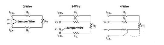
When there are more than two wires, these extra wires are only used to connect to the excitation source. In the 3-wire or 4-wire connection method, wiring is included in the high-impedance path of the measurement device, which effectively reduces errors caused by the wiring impedance.
The easiest way to connect a thermistor to a measurement device is using 2-wire connection (see Figure 3). In this method, the two wires that apply an excitation source to the thermistor can also be used to measure the voltage flowing through the sensor. Because the nominal impedance of the thermistor is very high, the impedance of the cables will not affect the accuracy of the measurement; therefore, the 2-wire measurement is sufficient for the thermistor, making the 2-wire thermistor the most commonly used.

2. Connect the Thermistor with the Device
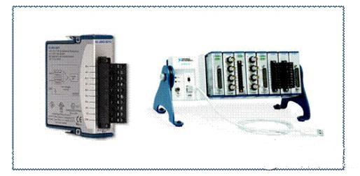
Many instruments offer similar options for connecting to a thermistor. Take NI CompactDAQ system and the NI 9215 C Series module as an example (see Figure 4).
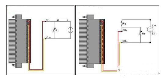
Note that the differential connection in the connection diagram in Figure 5─the two wires are connected to either end of the thermistor and the positive or negative terminal of the signal path (pin 0 and pin 1). When using this type of sensor for data acquisition, you can specify the excitation current (IEX) or excitation voltage (VEX) depending on the type of excitation source you are using.
The reading of the voltage difference across this resistor can be regarded as the temperature value. The relation between voltage and temperature across the resistor are not perfectly linear. To map the thermistor impedance to temperature, the NI-DAQmx driver uses a Steinhart-Hart thermistor third-order approximation formula.
You can use an external signal source, such as a C-Series voltage output module or current output module, to apply stimulus. Because the thermistor has a very high nominal impedance, you need a signal source that can accurately output low current. The NI 9265 C Series analog output module can be used as the current excitation source by placing it on the same NI cDAQ-9172 backplane as the C Series module that collects the readings. The NI 9265 has an output range from 0 to 20 mA with 16-bit accuracy. This unique output module has the same number of channels as the input module for temperature readings.
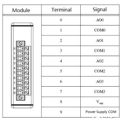
The output pins used by the C series current output module are shown in Figure 6.
If you are unable to dissipate the extra heat, the heat caused by the excitation current will make the temperature of the sensor element to rise above the ambient temperature, introducing errors into the reading of the ambient temperature. You can minimize the effects of self-heating by reducing the excitation current.
The signals generated by thermistors are usually on the magnitude of millivolts, which makes them vulnerable to noise interference. In the thermistor data acquisition system, a low-pass filter is usually used to effectively filter out high-frequency noise in the thermistor measurement. For example, low-pass filters are useful for remove the extremely common 60 Hz power line noise in most laboratories and factories.
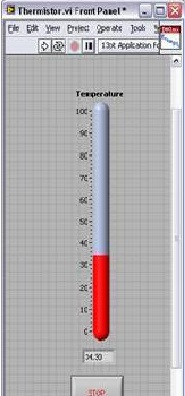
3. View Your Measurements: NI LabVIEW
Once the system configuration is properly completed, you can use the LabVIEW graphical programming environment to acquire and view data.
Related Source:
