Featured

Why is Wireless Charging of Mobile Phones Not Yet Popular?

Why is Wireless Charging of Mobile Phones Not Yet Popular?

Be yourself; Everyone else is already taken.

— Oscar Wilde.

This is the first post on my new blog. I’m just getting this new blog going, so stay tuned for more. Subscribe below to get notified when I post new updates.

As we all know, electronic products such as mobile phones and tablet computers have brought a lot of convenience to everyone’s life, but frequent charging problems are a headache. One charging cable and one charging head with different size and shape. If you go out without it, you are likely to fall into the embarrassing situation of “losing contact.”

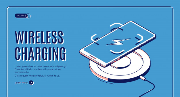
As early as October 2017, the wireless charging mobile phone family welcomed three new members: iPhone 8, iPhone 8 Plus and iPhone X. With its strong influence, Apple has also brought wireless charging technology into the eyes of everyone.

Wireless charging technology has inherent advantages – convenience, it can avoid the phenomenon of “ignition” when plugging and unplugging the charging line, which has no damage to the charging port, and makes the mobile device become one of the earliest “users” of wireless charging technology.

However, how has it passed so long, there are still many people who choose not to trust “wireless charging technology” and insist on charging lines.

From being invented to today, after 140 years of wireless charging technology, we unknowingly “sneaked” into our lives: not only small electronic devices such as mobile phones, tablets, smart watches, but also large equipment such as electric cars. They have all become members of the wireless charging family.

So, let’s first understand how wireless charging is implemented!

Three Principles of Wireless Charging

  1. Electromagnetic induction wireless charging — too short transmission distance

With the popularity of small electronic products such as mobile phones and the promotion of companies such as Texas Instruments, Philips, Samsung, and Toshiba, electromagnetic induction charging technology has become the most widely used wireless charging technology in small electronic products such as mobile phones.

As the name suggests, electromagnetic induction wireless charging technology uses the principle of electromagnetic induction. This charging system consists mainly of two coils: a primary coil and a secondary coil. First, the primary coil is supplied with a certain frequency of alternating current. Due to the electromagnetic induction, a certain current is generated in the secondary coil, so the energy is transferred from the transmission end to the receiving end.

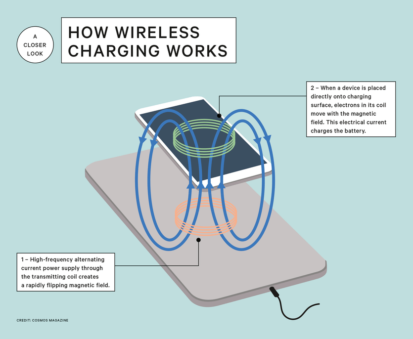
Applying this principle to the mobile phone, there is a primary coil in the charging base, and a secondary coil is built in the mobile terminal. When the mobile phone is close to the charging stand, based on the electromagnetic induction, a certain current is generated in the receiving coil of the mobile phone, and the mobile phone can be charged without the charging line.

However, electromagnetic induction wireless charging technology also has great shortcomings, the most troublesome of which is the limited transmission distance. Currently, this technology has an effective charging distance of only 10 mm, and if the two coil positions are not aligned, problems are likely to occur.

  • Magnetic resonance wireless charging — long transmission distance, high power supply efficiency, but need to be frequency modulated

On June 7, 2007, the research team of the Massachusetts Institute of Technology published the results in Science, saying: Successfully “caught” the electromagnetic wave. They used a copper coil as an electromagnetic resonance device, and the transmitting side sent electromagnetic waves of a specific frequency, and then spread the electromagnetic field to the receiving side, and successfully supplied power to a 60-watt bulb that was two meters away.

Therefore, two devices are also required to use such charging: an energy transmitting device and an energy receiving device. And the condition for energy transfer is that the two devices need to be adjusted to the same frequency. For example, two coils act as resonators, and the transmitting end vibrates to the surrounding electromagnetic field at a frequency of 10 MHz, and the receiving end also needs to vibrate at the same frequency of 10 MHz to realize energy transmission.

The magnetic vibrator is composed of a large inductance coil in which small capacitors are connected in parallel or in series. Compared to electromagnetic induction, magnetic resonance wireless charging has a longer transmission distance, higher power supply efficiency, and supports a one-to-many power supply mode. But the biggest difficulty is how to get the same frequency for both circuits. Frequency modulation is the most important step in this technology.

  • Radio wave transmission — transmission distance up to 10 meters, but low efficiency

The principle of transmitting electricity by radio waves is to convert electromagnetic waves into currents and then pass current through the circuit. The radio wave transmission system is mainly composed of a microwave transmitting device and a microwave receiving device. The microwave transmitting device emits radio waves, and the microwave receiving device captures radio wave energy and adjusts with the load to obtain stable direct current.

In theory, the wireless charging mode transmission distance is farther than the electromagnetic induction mode and the magnetic resonance mode, and can reach more than 10 meters; and it can also realize automatic charging anytime and anywhere. However, this method also has a big disadvantage, that is, relatively low transmission efficiency.

Reasons why wireless charging technology is not popular

Although the wireless charging technology for mobile phones has been proposed for a long time, it is puzzling: After so many years, this technology is still slow, why?

  1. Limited charging distance

Ordinary mobile phone charger with a charging cable, as well as a suitable charging head or charging treasure; while wireless charging has developed over the years and is only wireless charging within a few tens of millimeters, which means that we still need to bring a charging treasure or a charging head when we go out.

  • The stability and efficiency of wireless charging is difficult to achieve

Taking Apple’s 5W wireless charger as an example, considering the transmission efficiency, it takes about 3 hours to fully charge the iPhoneX; it takes nearly 2.5 hours to charge with the 7.5W wireless charger. Although 20W wireless chargers and wireless charging treasures appeared on the market in 2019, its stability and charging efficiency are still a big problem that lingers in the minds of consumers.

  • The impact of wireless charging on battery life

Although wireless charging technology has been developed for many years, the largest share of the market is still in the mobile phone field. Therefore, we have to consider: Will wireless charging shorten the service life of mobile phone batteries?

However, because of the wireless charging, we have no trouble with the complicated charging line. Wireless charging treasure can give your mobile phone “power” anytime, anywhere, so wireless charging can greatly facilitate our lives. Perhaps there are still some shortcomings in mobile wireless charging at this stage, but we believe in the power of technology, which will allow us to charge mobile phones and computers anytime, anywhere, in the near future.

How to Measure a Thermistor?

I Overview of Thermistors

Like Resistance Temperature Detectors(RTDs), thermistors are temperature-sensitive semiconductors whose impedance changes with temperature. Thermistors are manufactured from metal oxide semiconductor materials packed with glass or epoxy beads. Moreover, the typical nominal impedance value of thermistor is much higher than that of the RTD, which is from 2000Ω to 10,000Ω, so it can be used for lower current measurement.

Figure 1. Commonly Used Symbols for Thermistors

Each sensor has a given nominal impedance, which is approximately processed according to a certain linearization, and this impedance varies proportionally with temperature. The thermistor has a negative temperature correlation coefficient (NTC) or a positive temperature correlation coefficient (PTC). The former one is more common, and the impedance decreases with increasing temperature, while the latter increases with increasing temperature.

You can use a PTC thermistor as a current-limiting device (instead of a fuse), or as a heating component for a small temperature-controlled furnace. The NTC thermistor (the subject of this article) is mainly used for temperature measurement, and is widely used in digital temperature adjusting devices or automobiles to monitor the temperature of the engine.

Typically, the thermistor has a high sensitivity (about 200Ω/ °C), which makes it very sensitive to the changes in temperature. Although the thermistor has a very high response rate, its use is limited to a temperature range up to 300°C. This characteristic and its high nominal impedance help to provide accurate measurements in lower temperature applications.

II How to Measure a Thermistor?

1. Selection of Connecting Method

Since the thermistor is an impedance device, you must apply an excitation source to it, and then read the voltage flowing through the terminal. The excitation source must be kept constant and of considerable accuracy.

You can connect the thermistor differentially to an analog input channel for temperature measurement. In other words, you must connect the thermistor to the + ve and -ve terminals of the analog input channel.

The thermistor can be used in 2-wire, 3-wire, or 4-wire configurations, and their connections are shown in Figure 2.

Figure 2. Block diagram of 2-wire, 3-wire and 4-wire Connection

When there are more than two wires, these extra wires are only used to connect to the excitation source. In the 3-wire or 4-wire connection method, wiring is included in the high-impedance path of the measurement device, which effectively reduces errors caused by the wiring impedance.

The easiest way to connect a thermistor to a measurement device is using 2-wire connection (see Figure 3). In this method, the two wires that apply an excitation source to the thermistor can also be used to measure the voltage flowing through the sensor. Because the nominal impedance of the thermistor is very high, the impedance of the cables will not affect the accuracy of the measurement; therefore, the 2-wire measurement is sufficient for the thermistor, making the 2-wire thermistor the most commonly used.

Figure 3. 2-wire Connection

2. Connect the Thermistor with the Device

Many instruments offer similar options for connecting to a thermistor. Take NI CompactDAQ system and the NI 9215 C Series module as an example (see Figure 4).

Figure 4. NI 9215 C Series Analog Input Module and NI CompactDAQ Backplane

Note that the differential connection in the connection diagram in Figure 5─the two wires are connected to either end of the thermistor and the positive or negative terminal of the signal path (pin 0 and pin 1). When using this type of sensor for data acquisition, you can specify the excitation current (IEX) or excitation voltage (VEX) depending on the type of excitation source you are using.

Figure 5. NI 9215 Thermistor connection diagram with different external excitation, where (a) is the current excitation source and (b) is the voltage excitation source.

The reading of the voltage difference across this resistor can be regarded as the temperature value. The relation between voltage and temperature across the resistor are not perfectly linear. To map the thermistor impedance to temperature, the NI-DAQmx driver uses a Steinhart-Hart thermistor third-order approximation formula.

You can use an external signal source, such as a C-Series voltage output module or current output module, to apply stimulus. Because the thermistor has a very high nominal impedance, you need a signal source that can accurately output low current. The NI 9265 C Series analog output module can be used as the current excitation source by placing it on the same NI cDAQ-9172 backplane as the C Series module that collects the readings. The NI 9265 has an output range from 0 to 20 mA with 16-bit accuracy. This unique output module has the same number of channels as the input module for temperature readings.

The output pins used by the C series current output module are shown in Figure 6.

Figure 6. Terminal Connections of I 9265 Analog Output Module

If you are unable to dissipate the extra heat, the heat caused by the excitation current will make the temperature of the sensor element to rise above the ambient temperature, introducing errors into the reading of the ambient temperature. You can minimize the effects of self-heating by reducing the excitation current.

The signals generated by thermistors are usually on the magnitude of millivolts, which makes them vulnerable to noise interference. In the thermistor data acquisition system, a low-pass filter is usually used to effectively filter out high-frequency noise in the thermistor measurement. For example, low-pass filters are useful for remove the extremely common 60 Hz power line noise in most laboratories and factories.

3. View Your Measurements: NI LabVIEW

Once the system configuration is properly completed, you can use the LabVIEW graphical programming environment to acquire and view data.

Figure 7. Reading of Thermistor on LabVIEW Front Panel

Related Source:

All You Have to Know about NTC Thermistors

The Difference Between Polarized And Non-polarized Capacitors

The difference in performance and principle structure

Same in principle: (1) They both store and release charges; (2) The voltage on the electrode plate (here, the electromotive force accumulated by the charge is called voltage) cannot be abruptly changed.

The difference lies in the different media, different performance, different capacity, different structures, and different use environments and uses. On the other hand, according to the needs of production practice, people have experimentally manufactured capacitors with various functions to meet the normal operation of various electrical appliances and the operation of new equipment. With the development of science and technology and the discovery of new materials, better and more diverse capacitors will continue to emerge.

Different media: What is a dielectric? In fact, the material between the two plates of the capacitor has a polar capacitor. Most of the electrolyte is used as the dielectric material. Usually, a capacitor with the same volume has a large polar capacitor. In addition, the polarized capacitors produced by different electrolyte materials and processes will have different capacities in the same volume. There is also a close relationship between the withstand voltage and the use of dielectric materials: there are many non-polar capacitor dielectric materials, most of which use metal oxide films, polyester, etc. Due to the reversible or irreversible performance of the medium, the use environment of polar and non-polar capacitors is determined.

Different performance: Performance is the requirement for use, and maximum demand is the requirement for use. If a metal oxide film capacitor is used for filtering in the power supply part of a TV, and the capacitor capacity and withstand voltage required by the filtering must be achieved, I am afraid that only a power supply can be installed in the cabinet. Therefore, only polarized capacitors can be used for filtering, and polarized capacitors are irreversible. In other words, the positive electrode must be connected to the high potential terminal, and the negative electrode must be connected to the low potential terminal. Generally, the electrolytic capacitor is above 1 microfarad for coupling, decoupling, and power supply filtering. The non-polar capacitors are mostly below 1 microfarad and participate in resonance, coupling, frequency selection, current limiting, etc. Of course, there are also large-capacity and high-withstand voltage, which are mostly used for reactive compensation of power, phase shift of motors, and shift of variable-frequency power.

Different structures: In principle, regardless of the tip discharge, any shape of capacitor can be used in the environment. The commonly used electrolytic capacitors (with polar capacitors) are round, and square ones are rarely used. Non-polar capacitors have various shapes, such as tube type, deformed rectangle, sheet type, square type, round type, combined square type and round type. Of course, there are intangibles. The intangibles here refer to distributed capacitance. The distributed capacitance must not be ignored in high frequency and intermediate frequency devices.

The ideal capacitor is originally non-polar. However, in practice, in order to obtain large capacity, some special materials and structures are used, which leads to the fact that some actual capacitors are polarized. Common polar capacitors include aluminum electrolytic capacitors and tantalum electrolytic capacitors. Electrolytic capacitors are generally relatively large in capacity, so if you want to make a large-capacity non-polar capacitor, it will not be so easy and the volume will become very large. This is why in actual circuits, there are so many polar capacitors. Because it is relatively small and the voltage in such a circuit has only one direction, a polarized capacitor can come in handy. We use polar capacitors to avoid its disadvantages and to take advantage of them. We can also understand in this way: a polarized capacitor is actually a capacitor that can only be used in one voltage direction. Non-polar capacitors can be used in both voltage directions. Therefore, from the point of voltage direction alone, non-polar capacitors are better than polar capacitors.

The most basic structure of electrolytic capacitors is polar, which is determined by the production process. Compared with non-polar capacitors, the principle characteristics of electrolytic capacitors make it easy to achieve large capacity with less material and smaller volume. However, because of its polarity, it can only be applied to a certain DC component, but it is not suitable for pure AC. The polarity of the electrolytic capacitor must conform to the direction of the DC component and cannot be used in reverse. An alternative type of electrolytic capacitor is a non-polar electrolytic capacitor. This electrolytic capacitor can also be used for pure AC like ordinary non-polar capacitors, and can have a larger capacity than a capacitor in the same volume, but the volume is about twice as large as that of the same capacity with polar electrolysis. After all, it is the technology of electrolytic capacitors, so its AC characteristics cannot be completely aligned with that of capacitors. It lies between capacitors and electrolysis. Compared with capacitors and polar electrolytic capacitors, the use conditions of non-polar electrolytic capacitors are more severe. And when it is applied, it should be treated more as an electrolysis. It can be seen from the above analysis that it is perfectly possible to use a non-polar capacitor instead of a polar capacitor. As long as the capacity, working voltage, and volume can meet the requirements, they can be replaced.

Polarized capacitor refers to a type of capacitor such as electrolytic capacitor. It is formed by the anode’s aluminum foil and the cathode’s electrolyte respectively, and then a layer of aluminum oxide film produced on the anode’s aluminum foil is used as the dielectric capacitor. Due to this structure, it has a polarity. When the capacitor is connected in the positive direction, the aluminum oxide film will remain stable due to the electrochemical reaction; when it is connected in the reverse direction, the aluminum oxide layer will become thin, making the capacitor easily damaged by breakdown. So the electrolytic capacitor must pay attention to the polarity in the circuit. But ordinary capacitors are non-polar, so the anode or cathode of two electrolytic capacitors can be connected in series to form a non-polar electrolytic capacitor.

Is an electrolytic capacitor in series a non-polar capacitor?

Of course, the method of two electrolytic capacitors in parallel cannot work, and the two electrolytic capacitors in series are still not working without proper bias voltage. And adding a bias voltage is quite complicated, especially if the capacitor (two series) are not grounded at both ends (the bias voltage must be floating). Considering the complexity of adding a bias voltage, it is better to use this method: connect two capacitors with negative stages, and connect a high-current diode to the two capacitors.

Of course, there is polarity in parallel. If anti-parallel, it is non-polar, but it is non-polar that cannot be used. If it is reverse series, it is not advisable, because if you do the experiment, you will find that there must be a capacitor to withstand the reverse voltage. If the voltage is large, it will blow up. Unless you have special measures that always allow the voltage to be applied to the capacitor that bears the positive voltage. There have been related records that two electrolytic capacitors of the same capacity can be connected in series, but a diode must be connected in anti-parallel to prevent reverse breakdown of the electrolytic capacitor. Later it turned out that the effect was ok. 

Introduce Yourself (Example Post)

This is an example post, originally published as part of Blogging University. Enroll in one of our ten programs, and start your blog right.

You’re going to publish a post today. Don’t worry about how your blog looks. Don’t worry if you haven’t given it a name yet, or you’re feeling overwhelmed. Just click the “New Post” button, and tell us why you’re here.

Why do this?

  • Because it gives new readers context. What are you about? Why should they read your blog?
  • Because it will help you focus you own ideas about your blog and what you’d like to do with it.

The post can be short or long, a personal intro to your life or a bloggy mission statement, a manifesto for the future or a simple outline of your the types of things you hope to publish.

To help you get started, here are a few questions:

  • Why are you blogging publicly, rather than keeping a personal journal?
  • What topics do you think you’ll write about?
  • Who would you love to connect with via your blog?
  • If you blog successfully throughout the next year, what would you hope to have accomplished?

You’re not locked into any of this; one of the wonderful things about blogs is how they constantly evolve as we learn, grow, and interact with one another — but it’s good to know where and why you started, and articulating your goals may just give you a few other post ideas.

Can’t think how to get started? Just write the first thing that pops into your head. Anne Lamott, author of a book on writing we love, says that you need to give yourself permission to write a “crappy first draft”. Anne makes a great point — just start writing, and worry about editing it later.

When you’re ready to publish, give your post three to five tags that describe your blog’s focus — writing, photography, fiction, parenting, food, cars, movies, sports, whatever. These tags will help others who care about your topics find you in the Reader. Make sure one of the tags is “zerotohero,” so other new bloggers can find you, too.

Design a site like this with WordPress.com
Get started